DMVPN // Building a Scalable Multi-Tenant Phase-3 DMVPN Headend
For whatever reason, I end up supporting technology for a lot of events, some simultaneously. A lot of times, when you’re using Telepresence endpoints for events, remote hands-on labs, etc. you want to be able to have separation between events so that one group doesn’t break another group’s stuff. At the same time, I don’t want to have to be deploying 30 different routers in my DMZ for 30 different events; it’s just an administrative nightmare. Instead, what we opted for, was to use multi-tenanted DMVPN headend for site-to-site connectivity.
What is DMVPN? And why DMVPN over traditional site-to-site VPN?
If you already know what DMVPN is, as well as it’s history, then skip this section. DMVPN as a technology has come pretty far from it’s first iteration (phase 1). Since then we’ve had two more iterations (phases 2 and 3, respectively).
DMVPN itself is a pretty old technology; it uses the Next-Hop Resolution Protocol (NHRP) - which basically is a discovery mechanism for the hubs and spokes in the DMVPN cloud, and works a little bit differently than your typical site-to-site VPN. First, and most notably, the client/spoke router establishes a connection to the headend router, instead of them mutually establishing a connection to each other. This has some pretty neat consequences:
-
First, you don’t need to have a static IP on the client spoke router (or branch router). Unlike traditional site-to-site VPN; the headend doesn’t try to connect to the client, the client can come in from any IP address, and register itself to the NHRP directory (obviously with some security measures around it)
-
Next, because the client is the one initiating the connection to the server, we can traverse through NAT; which makes it great when I send a router to an organization, not knowing anything about their infrastructure. Barring security policies that stop DMVPN (e.g. isakmp [500/udp], non500-isakmp [4500/udp], IP Protocol 50, etc.), the router I ship over can pretty much tunnel through whatever networks; whether their NATted network, a direct WAN connection, traversing through their MPLS network, then hitting their internet, DHCP, static IP, whatever…the router can tunnel through
As an example, when I built a mobile venue on a train, I had a DMVPN client router on the train, using a cellular modem, on the provider’s NATted cell network (If I were to guess, it was NATted a few times…), and utilized a router sitting in a datacenter with VPN capabilities so that I could connect to the venue remotely and make changes if required from the comfort of wherever I was. In a case like that, there was no way I could use a traditional site-to-site VPN since I was at the mercy of the provider’s DHCP address, behind NAT.
With phase 2 and phase 3, you can also do some neat things like preserve Quality of Service (QoS) markings across the tunnel, enable multicast across the tunnel (and proper routing protocols that leverage multicast).
Basic Router Configuration
First, we need to get some basic configuration on the routers to make sure the devices can get out, and to make sure that we can manage the devices securely. This includes things like NAT, VLANs, IP addressing, and SSH. I also added a separate management VRF on the headend that connects back to my management infrastructure, and I can use this for SSH, SNMP, Netflow, etc.
vrf definition MGMT
 description ** OUT OF BAND MGMT ONLY **
 !
 address-family ipv4
 exit-address-family
!
interface GigabitEthernet0/1
 description ** OUT OF BAND MGMT ONLY **
 vrf forwarding MGMT
 ip address <IP> <SUBNET>
I’m not going to go through everything for the basics, as there are many guides on basic router setup and hardening. I will say though, I typically find the Cisco CLI Analyzer tool quite useful for finding if I missed something up from a router-hardening perspective, and for general troubleshooting. You can find it at http://cway.cisco.com/go/sa.
VRF and FVRF
As part of our security posture, and isolation requirements, we decided it would be best if we implemented a Front Door VRF (FVRF), as well as multiple VRF’s to separate the clients. This way, if there’s a provider that has any issues, etc., our routes don’t necessarily get leaked out, and vice versa . This also helps to protect our internal networks in the event that someone on the untrusted WAN accidentally stumbles their way onto our routing tables! The idea of a FVRF is that it acts as a front door and stops unwanted routes, etc. from getting fat-fingered in. That VRF only contains the default-route out, and any routing required for the ISP. Note that the only interface in the FVRF is the outside interface. The tunnel interfaces, and any other interfaces will be configured on separate VRF’s and the default routes will be leaked out to point to the FVRF. FVRF’s are also great when you have multiple outbound interfaces. You isolate the different WAN links (whether Internet, MPLS, LTE, etc), and ensure that tunnel interfaces, etc. use the right outbound interfaces without creating route recursion issues.
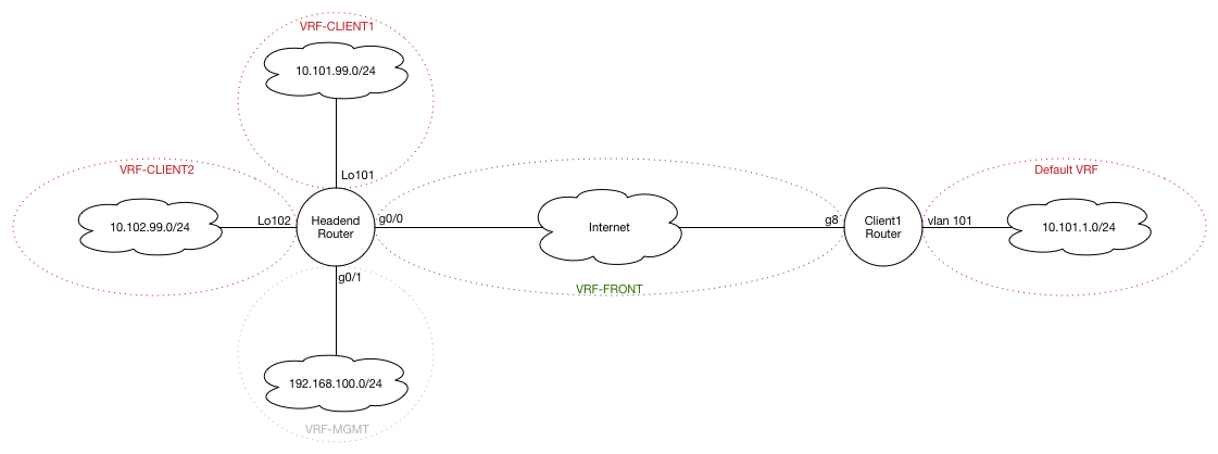
On the headend router, we’re going to create multiple VRF’s (to support multiple tenants; since that’s sort-of the premise of this post…), and on the client router, we’re only going to have one tenant, and as such, we’ll only need to create the FVRF to separate these networks from the untrusted WAN. The internal traffic can use the default global IP route table. If there was ever a need to support multiple clients, at that point, it would just mean that we create multiple VRF’s then. Not a huge deal. Also – keep in mind that VRF’s are locally significant so they don’t necessarily need to match (though you would probably want it to for consistency’s sake).
Also note that when you apply the “vrf forwarding
Let’s start – first we’re going to define the FVRF on the Headend and Client routers, and enable the IPv4 address familes on them. We’ll allow multicast by creating a multicast address-family on the Tenant VRF as well:
Headend:
vrf definition VRF-FRONT
 description ** FRONT-DOOR VRF **
 !
 address-family ipv4
 exit-address-family
vrf definition VRF-TENANT1
 description ** TENANT ONE **
 ipv4 multicast multitopology ! Our requirements needed to support Multicast – plus makes routing a little cleaner
 !
 address-family ipv4
 exit-address-family
 !
 address-family ipv4 multicast
 exit-address-family
!
interface GigabitEthernet0/0
 description ** WAN INTERFACE **
 vrf forwarding VRF-FRONT
 ip address x.x.x.x x.x.x.x !If you already had an IP address configured, don’t forget to re-add it!
Client Router:
vrf definition VRF-FRONT
 description ** FRONT-DOOR VRF **
 ipv4 multicast multitopology
 !
 address-family ipv4
 exit-address-family
 !
 address-family ipv4 multicast
 exit-address-family
!
interface GigabitEthernet8
 description ** INTERNET **
 vrf forwarding VRF-FRONT
 ip address dhcp client-id GigabitEthernet8
 ip nat outside
!
Don’t forgot to add your default routes on both routers either:
ip route vrf MGMT 0.0.0.0 0.0.0.0 x.x.x.x ! We’re only doing this on our hub router
ip route vrf VRF-FRONT 0.0.0.0 0.0.0.0 x.x.x.x
If you noticed, we created the Tenant-1 VRF as well above on the hub router. When we create the virtual tunnel interface (VTI) on the hub later, we have to make sure that we define the FVRF in the VTI so that the traffic is able to get out and respond to the client router and form the tunnel. We do this by adding the tunnel vrf VRF-FRONT command in the VTI configuration.
Zone-Based Firewall
Since our network traffic requirements were relatively light, and these routers are short-term devices, we decided to consolidate our deployment and run our stateful firewalling using the ISR’s built-in Zone-Based Firewall (ZBFW) capabilities. If this were a permanent installation with heavy traffic requirements, it would make more sense to deploy a dedicated next-generation firewall (NGFW) along side our routers. But since our goal is to deploy these routers and networks quickly, the ISR ZBFW works wonderfully.
Just some background if you aren’t familiar with ZBFW - as the name suggests, a Zone-Based firewall helps to manage traffic flows and communications between different logical “zones”. We can take multiple interfaces and group them together into zones and then define how those interface groups communicate with one another. Interfaces that are in the same zone can communicate feely with one another, however, traffic crossing zone boundaries requires us to set policies on how that traffic is treated.
On the client router, three main zones needed to be configured for our use case. The INSIDE zone, OUTSIDE zone, and the “self” zone. If you’re not aware, the self zone is a default zone that is built around the router’s control plane and management plane (i.e. connections to the router itself – like in this case how the router will be sending/receiving protocols like ICMP, ISAKMP, IPSEC, etc).
Using ACL’s is a great way of managing class maps for application-level stuff. It’s a little more efficient and adds some flexibility and structure (especially hen reviewing the config to troubleshoot!). So let’s by defining some ACL’s we want for letting the tunnels through, management, etc:
ip access-list extended ACL-DHCP-IN
 permit udp any eq bootps any eq bootpc
!
ip access-list extended ACL-DHCP-OUT
 permit udp any eq bootpc any eq bootps
!
ip access-list extended ACL-ESP
 permit esp any any
!
ip access-list extended ACL-GRE
 permit gre any any
!
ip access-list extended ACL-IPSEC
 permit udp any any eq non500-isakmp
 permit udp any any eq isakmp
!
ip access-list extended ACL-MANAGEMENT
 permit tcp any any eq 22
 permit udp any any eq ntp
!
ip access-list extended ACL-PING-AND-TRACEROUTE
 permit icmp any any echo
 permit icmp any any echo-reply
 permit icmp any any ttl-exceeded
 permit icmp any any port-unreachable
 permit udp any any range 33434 33463 ttl eq 1
Hopefully the ACL names should lend themselves to explaining what the ACL’s do.
In my case, I’m sticking with some basic class maps, which will select what traffic gets inspected or passed (i.e. passed through without necessarily holding state – i.e. UDP traffic for the most part). I’m defining these classes as I would zone-pairs, which is the mechanism that allows different zones to communicate.
class-map type inspect match-any CLASS-OUTSIDE-TO-SELF-PASS
 match access-group name ACL-ESP
 match access-group name ACL-DHCP-IN
 match access-group name ACL-GRE
!
class-map type inspect match-any CLASS-SELF-TO-OUTSIDE-PASS
 match access-group name ACL-ESP
 match access-group name ACL-DHCP-OUT
 match access-group name ACL-GRE
!
class-map type inspect match-any CLASS-OUTSIDE-TO-SELF-INSPECT
 match access-group name ACL-IPSEC
 match access-group name ACL-MANAGEMENT ! Note that we have SSH enabled on our WAN interface in – that was for my specific case – this isn’t recommended in production environments!
!
class-map type inspect match-any CLASS-SELF-TO-OUTSIDE-INSPECT
 match access-group name ACL-IPSEC
 match access-group name ACL-PING-AND-TRACEROUTE
 match access-group name ACL-MANAGEMENT
!
class-map type inspect match-any CLASS-INSIDE-TO-OUTSIDE-INSPECT
 match protocol tcp
 match protocol udp
 match protocol icmp
Next, we need to put these class maps into policy maps, so that the policies can be applied.
policy-map type inspect POLICY-OUTSIDE-TO-SELF
 class type inspect CLASS-OUTSIDE-TO-SELF-INSPECT
  inspect
 class type inspect CLASS-OUTSIDE-TO-SELF-PASS
  pass
 class class-default
  drop
policy-map type inspect POLICY-INSIDE-TO-OUTSIDE
 class type inspect CLASS-INSIDE-TO-OUTSIDE-INSPECT
  inspect
 class class-default
  drop
policy-map type inspect POLICY-SELF-TO-OUTSIDE
 class type inspect CLASS-SELF-TO-OUTSIDE-INSPECT
  inspect
 class type inspect CLASS-SELF-TO-OUTSIDE-PASS
  pass
 class class-default
  drop log
As you can see, we either inspect, pass or drop all traffic. In this case, inspect means that we keep track of the traffic leaving the zone and allow the response traffic to come back in (i.e. this is the “state” in a stateful firewall, rather than just allowing the traffic out one way (unilaterally).
Now we can build our zones. I usually do this first, but it can be done either before or after the above steps.
zone security INSIDE
 description ** Internal Network Zone **
zone security OUTSIDE
 description ** External UNTRUSTED Zone **
As I mentioned above, the self zone doesn’t need to be defined, as it already exists. Lastly, we add the zones to the interfaces, and create our zone-pairs to allow the traffic we specified through between zones. Note the policy maps we created before are applied in the service policy for each zone.
! Apply Zones to Interfaces

interface <OUTSIDE_INTERFACE>
 description ** INTERNET **
 zone-member security OUTSIDE
!
interface <INSIDE_INTERFACE>
 description ** INTERNAL NETWORK **
 zone-member security INSIDE


! Build Zone Pairs to Allow Traffic Across

zone-pair security ZONE-INSIDE-TO-OUTSIDE source INSIDE destination OUTSIDE
 service-policy type inspect POLICY-INSIDE-TO-OUTSIDE
!
zone-pair security ZONE-OUTSIDE-TO-INSIDE source OUTSIDE destination INSIDE
!
zone-pair security ZONE-SELF-TO-OUTSIDE source self destination OUTSIDE
 service-policy type inspect POLICY-SELF-TO-OUTSIDE
!
zone-pair security ZONE-OUTSIDE-TO-SELF source OUTSIDE destination self
 service-policy type inspect POLICY-OUTSIDE-TO-SELF
And there it is! Zone-based firewall done! As a note – this config is from my client router, but I used it on the headend router as well, but with different zones (i.e. Tenant-1, Tenant-2, etc. instead of Inside). One thing I learnt while doing this is that zones must be in the same VRF (i.e. you can’t have one INSIDE zone for all your tenants; you need separate ones between VRF’s…which is probably for the best anyways)
Phase 3 DMVPN
As I previously mentioned, DMVPN as a technology has come a long way. In phase-1, the communication was very basic, where there really wasn’t much in the way of spoke-to-spoke communication. Though spokes could discover themselves dynamically, the path was persistent through the hub. In other words, all traffic flowed through the hub. With phase-2 came the ability to dynamically build spoke-to-spoke tunnels, where the hub basically just acted as a directory to point to other spokes, if the spoke needed to send information to another spoke. With phase-2 also introduced tiered-hubs, where you can have spokes, regional hubs where the spokes connect, and global hubs that connect the regional hubs. In phase-2, moving traffic between the hubs flowed through the global hub (similar to how phase-1 worked), but phase-3 introduces spoke-to-spoke communication even between spokes separated by different regional hubs.
Phase-3 DMVPN itself is pretty easy to set up and just kind-of works. Actually pretty refreshing – this was about the only thing we didn’t have to test ten times over and tweak again and again since it just picked up and worked. Note: this doesn’t include securing the tunnel, whose configuration still sucks. Let’s start by creating the tunnel interface on the hub and putting it on its own tenant VRF + zone:
interface Tunnel0
 description ** DMVPN TUNNEL **
 vrf forwarding VRF-TENANT1
 ip address 172.16.100.1 255.255.255.0
 no ip redirects
 zone-member security ZONE-TENANT1
We also want to adjust the MTU and MSS to accommodate the overhead from the mGRE and IPSec headers :
interface Tunnel0
 ip tcp adjust-mss 1360
 ip mtu 1400
Now we want to do the NHRP configuration on the headend. For the most part, the commands are pretty straight forward.
Let’s start by defining the tunnel network properties. The network ID is locally significant (but recommended to be the same within each DMVPN network. In my case, we also need to support multicast traffic, so we enable that as well. Lastly, we also want to define the tunnel as a multipoint GRE (mGRE) tunnel.
interface Tunnel0
 ip nhrp map multicast dynamic ! Allow Multicast traffic
 ip nhrp network-id 1
 tunnel source GigabitEthernet0/0 ! Physical WAN interface
 tunnel mode gre multipoint
We want to allow dynamic spoke-to-spoke communications by allowing NHRP redirects (this is a phase-3 configuration command). We’re also going to add a tunnel key – think of this as a means to separate each tenant. It’s an optional command, which, if you’re not having multiple-tenants, you don’t need. On the spoke, you’ll notice it’s the same tunnel key; it is not locally significant.
interface Tunnel0
 ip nhrp redirect
 tunnel key 0 ! Must match globally to identify network
 tunnel vrf VRF-FRONT ! Leak FVRF information so the tunnel knows what VRF to look in at in order to find its far end tunnel peer (over the internet to the spoke router)
Lastly, I’m going to add authentication for some basic protection and tweak the NHRP hold timer to 300 seconds, which is recommended. The default is 600s, or 10 minutes.
interface Tunnel0
 ip nhrp authentication <NHRP_KEY>
 ip nhrp holdtime 300
On the spoke, the commands are very similar, except we define the Hub IP address, and instead of using ip nhrp redirect, we use ip nhrp shortcut, to tell the router to use shortcuts (i.e. spoke-to-spoke communication)
interface Tunnel0
 ip address 172.16.100.2 255.255.255.0
 no ip redirects
 ip mtu 1400
 ip nhrp authentication <NHRP_KEY>
 ip nhrp network-id 1
 ip nhrp holdtime 300
 ip nhrp nhs <HUB_TUNNEL_IP> nbma <HUB_PUBLIC_IP> multicast
 ip nhrp shortcut
 zone-member security Inside
 ip tcp adjust-mss 1360
 tunnel source GigabitEthernet8
 tunnel mode gre multipoint
 tunnel key 0
 tunnel vrf VRF-FRONT
And that should be it!
Securing the tunnel
This is the part I dread the most.
First, we want to start by defining our keyrings. This part can be done per tenant, if you have the requirement that each tenant has its own authentication key , which should almost always be the case.
crypto ikev2 keyring IKEv2-KEYRING-TENANT1
 peer PEER-TENANT1
  address 0.0.0.0 0.0.0.0
  description ** TENANT 1 KEYRING **
  pre-shared-key <KEY>
Now we want to create the IKEv2 profile for the tenant. This would define what VRF to look at, who to connect to, what type of authentication to use, and where to look for the authentication.
crypto ikev2 profile IKEv2-PROFILE-TENANT1
 match fvrf VRF-FRONT ! Defines the FVRF to use for this profile. Using ‘any’ will use any of FVRF to accept connections to this profile (if you have multiple)
 match identity remote address 0.0.0.0 ! Use 0.0.0.0 since we don’t know what IP’s our remote connections will be coming from
 authentication local pre-share
 authentication remote pre-share
 keyring local IKEv2-KEYRING-TENANT1
 ivrf VRF-TENANT1 ! Needed on the headend to identify the Inside VRF since we’re not using the default VRF for Tenant 1
You can use the show crypto ikev2 profile command to review the settings.
After this part, we want to create the IPSec Transform Set. The TS basically defines what protocols to use to encrypt the traffic (authentication and encryption of the packets). This part is pretty simple, and I’m not going to go through the different protocols, since you can google that for the most up-to-date standards. At the time of writing, I used ESP with 256-bit AES encryption and ESP with the SHA-HMAC variant for authentication. Not saying these are the best, it’s just what I used.
crypto ipsec transform-set TS-SECURE-CIPHERS esp-aes 256 esp-sha-hmac
 mode transport
You’ll notice that the mode is set to transport, as tunnel-mode is the default and doesn’t really provide much benefit to us.
Now we want to use the IPSec Transform Set and combine that with the IKEv2 profile. We do this in the IPSec Profile (not to be confused with the IKEv2 Profile that we created above). We basically just need to define the Transform Set we used and the IKEv2 profile.
crypto ipsec profile IPSEC-PROFILE-TENANT1
 set transform-set TS-SECURE-CIPHERS
 set ikev2-profile IKEv2-PROFILE-TENANT1
We can now apply this profile onto the Tunnel Interface
interface Tunnel0
 tunnel protection ipsec profile IPSEC-PROFILE-TENANT1 shared
Doing this on all the routers gets us security and privacy on our DMVPN tunnels.
Note: Even though we’re not using IKEv1, it’s a good idea to turn off aggressive-mode key-exchange that’s used with IKEv1 by using the command: crypto isakmp aggressive-mode disable as aggressive mode is pretty insecure. It was created to make the negotiation more streamlined, but instead ends up being worse-off from a security-posture perspective, as it can be exploited.
Routing
The routing for this would be similar to how you would normally use routing, we just added the interfaces that we wanted to advertise and added the networks we needed to add. I decided to use named-EIGRP, since I found it a little more structured and more logical when working with VRF’s. A lot of people use BGP between WAN links, which is great. We just didn’t for this since we aren’t doing anything special with it.
! HUB
router eigrp EIGRP-TENANT1
 !
 address-family ipv4 unicast vrf VRF-TENANT1 autonomous-system 1
  !
  af-interface default ! Don’t advertise EIGRP from any interfaces by default
   passive-interface
  exit-af-interface
  !
  af-interface Tunnel0
   hello-interval 20
   hold-time 60
   no passive-interface ! Allow EIGRP from this interface
   no split-horizon ! We need to turn this off since there will be spilt-horizoning on this for EIGRP since we will have spoke-to-spoke communications on the same tunnel interface
  exit-af-interface
  !
  topology base
  exit-af-topology
  network <network> <optional_wildcard> ! Do this for each network
  eigrp router-id <router-id>
 exit-address-family

! SPOKE
router eigrp EIGRP-TENANT1
 !
 address-family ipv4 unicast autonomous-system 1
  !
  af-interface default ! Don’t advertise EIGRP from any interfaces by default
   passive-interface
  exit-af-interface
  !
  af-interface Tunnel0
   hello-interval 20
   hold-time 60
   no passive-interface ! Allow EIGRP from this interface
  exit-af-interface
  !
  topology base
  exit-af-topology
  network <network> <optional_wildcard> ! Do this for each network
  eigrp router-id <router-id>
 exit-address-family
Conclusion
All of what we’ve done here is actually as per the IWAN design guide. If you do this utilizing multiple WAN (Internet, Cell, MPLS) links, that’s technically a proper IWAN design. Some elements that are missing between this and the IWAN CVD are: Direct Internet Access, Performance Routing (PfR), and Policy-based Routing (PBR). I grabbed some stuff on here from the IWAN book, which I think is a great resource, and explains this stuff in pretty in-depth detail. You can find it on on Amazon.
Just want to give another shout out to Steven Harnarain again for helping out with this project and helping me painstakingly document all of this!